Introduction to Internet of Things
with Arduino and Python
About the Course
This course is an introduction to developing networked embedded systems. It will walk you through writing a program to collect data from a sensor with an Arduino UNO, sending that data to a computer over a serial connection, and then logging that data into a database.
By the end of this tutorial, you'll have a system collecting temperature data and reporting it to a database from which you can view historic plots of the data. This will give you a template from which you can record almost any type of data you could think of and get it into a saved format which can be easily analyzed later or for which actions can be triggered in real-time.
Notes On Using this Book Asynchronously
I originally wrote and developed this for the purpose of instructing the content live with hardware provided and an instance of the database accessible over LAN. If you're interested in following along remotely, check out the appendix items for a list of hardware you'll need to purchase and a non-comprehensive guide to setting up InfluxDB with Docker.
This Book is a Living Document
If you find a mistake, a broken link, or an opportunity to provide a better explanation, please file an issue on this course's GitHub repository!
Knowledge to Have Before the Course
This course assumes a small amount of prerequisite knowledge. While the content should be accessible if you've not programmed in Python or C++ before (the two languages the provided code are written in), the course will not explain the basics of programming. If you're taking the course with me in person, I've provided the hardware and no changes should be required. However if you're following along remotely, you'll need to be comfortable using a breadboard and perhaps soldering.
If you're new to programming, I suggest following along with the earlier chapters of Automate the Boring Stuff with Python by Al Sweigart. You can find the online version here. This will instruct you on how to install the tools, basics of programming like variables and functions, and basic concepts about the operating system and resources it makes available to you.
If you've new to electronics, Adafruit has put together a simple guide to getting started with Arduino and electronics in general. Naturally, they'll sell you a kit to do so, but similar kits are also available on Amazon or Sparkfun and from stores like Microcenter. I recommend shopping around as they contain various different kinds of hardware. Adafruit's course can be found here.
A Little About Myself
I've been developing embedded systems in industry for several years now working on smart home systems as well as in robotics. This is a field I've found to be very approachable for hobbyists and students due to the vast amount of information available online and the relatively low monetary cost of entry. I write about my projects in robotics and systems programming on my website if you're curious about my other projects or want updates as I write more courses (maybe).
Install Prerequisites
This page will walk you through installing all of the tools required for building the code for the Arduino and running the Python script on your host system.
Arduino IDE
I won't repeat too much information here which could easily go out of date and instead refer to Arduino's documentation for installing the Arduino IDE. Instructions there are available for Windows, macOS, and Linux.
Verify your installation by opening the IDE, creating a new sketch, and navigating the menu to Tools -> Board -> Arduino AVR Boards -> Arduino UNO. This is the board we'll be focusing on in this course. Then select the checkmark button in the top left and verify that the output window eventually finishes printing and shows something like below:
Sketch uses 444 bytes (1%) of program storage space. Maximum is 32256 bytes.
Global variables use 9 bytes (0%) of dynamic memory, leaving 2039 bytes for local variables. Maximum is 2048 bytes.
Ubuntu 22.04-based Linux Distros
A quick note that if you're using an unofficial Arduino, you'll find that the device does not actually mount as it's supposed to. If you run lsusb you might see an entry for CH340 or CP210x USB drivers, but no device at /dev/ttyACM0 or /dev/ttyUSB0. By default Ubuntu 22.04 and distributions based on it ship with a Braille reader software called brltty which is aggressive in claiming devices it thinks are Braille readers.
In dmesg, you might see something like this as a symptom:
input: BRLTTY 6.4 Linux Screen Driver Keyboard as /devices/virtual/input/input31
usb 1-8: usbfs: interface 0 claimed by ch341 while 'brltty' sets config #1
ch341-uart ttyUSB0: ch341-uart converter now disconnected from ttyUSB0
If you are not blind and no one who is blind is using your computer, feel free to uninstall it: sudo apt remove brltty. If you want to keep the software on your system for one reason or another, try:
sudo systemctl stop brltty-udev.service
sudo systemctl mask brltty-udev.service
sudo systemctl stop brltty.service
sudo systemctl disable brltty.service
Or if you use a Braille screen reader, you might just try editing the udev rules at /usr/lib/udev/rules.d/85-brltty.rules. For the CH340 (with USB VID and PID of 1a86:7523), remove the corresponding entry:
# Device: 1A86:7523
# Baum [NLS eReader Zoomax (20 cells)]
ENV{PRODUCT}=="1a86/7523/*", ENV{BRLTTY_BRAILLE_DRIVER}="bm", GOTO="brltty_usb_run"
Python and pip
Similarly, for installing python3 and pip, there are great directions available. Here is a link to Python's documentation for installation on various operating systems.
Verify your installation in two parts. First, python:
python3 --version
And then pip:
python3 -m pip -V
Both commands will print the versions of python3 and pip respectively.
Once both of those are installed, create a new folder for your project, something like iot_course, and inside download this file. Save it as requirements.txt. Then you can run python3 -m pip install -r requirements.txt from that directory to install the Python libraries we'll be using in this course.
Python Development Environment
Feel free to develop and execute the python code in whatever way is most comfortable for you. However, if you've never written python before, I recommend a free program called VSCode for editing and running. Downloads for all platforms are available here.
Once you've finished installing, navigate to the Extensions tab in the left column sidebar (icon shows three blocks together and an additional block by itself). There is an extension by Microsoft for Python which gives convenient ways of running Python scripts.
Blinking an LED
We'll get started on the Arduino side of things first since that will eventually be the source of the data. This is always a useful first step no matter how experienced you are with embedded systems as it verifies that your compiler and flashing toolchain is functional and that the basics of your hardware setup are correct. Luckily the Arduino UNO has an LED onboard for expressly this purpose.
Open your new sketch in the Arduino IDE, call it temperature_sensor or something like that. This should give you a file with two functions defined: setup and loop. Rather than defining a main function yourself, Arduino typically tries to hide some of these details in their attempt to be more user-friendly. I usually leave the loop function empty and treat setup as my main function. This means you don't need to define every as a global variable (since there's otherwise no way to reference variables in both functions).
Source Code
Let's start with this implementation to get an LED blinking, I'll explain what each line is doing down below.
void setup() {
    const int LED_PIN = 13;
    pinMode(LED_PIN, OUTPUT);
    bool led_state = false;

    while (true) {
        digitalWrite(LED_PIN, led_state);
        led_state = !led_state;
        delay(5000);
    }
}
The code can be explained in two parts. First we have the initialization step, making a constant variable with a good name of LED_PIN and assigning it to 13 since the Arduino's onboard LED is pin D13. We have to configure that GPIO pin on the microcontroller as an output (instead of an input) so that we can set that GPIO pin to logical high or low states (5 volts or 0 volts respectively). This is done with the pinMode function, whose documentation can be found here. Finally, we create a variable to represent the current state of the LED (false meaning off).
Next there's the looping code which will run forever as long as the board is powered (due to while (true) {}). In here, we use digitalWrite to set the LED's pin to our current LED state, then we flip the LED state with boolean logic. Finally, we add a delay since otherwise it would blink so fast that we'd never see it. The delay function takes an argument of milliseconds, so in this case there will be 5 seconds between changes to the LED.
Flashing Code to the Arduino
Use the Verify (checkmark) to compile the C++ source code (make sure you've chosen your Board first) and wait for a successful compile. If you've missed a semicolon or have another type of syntax error, the Output window on the bottom will show red text explaining the error that prevented compiling. It will also show warnings here in yellow text which can provide clues if your code doesn't function how you expect.
Plug in the board's USB cable to your computer and select the board's port via Tools -> Port. On Windows, it will be something like COM1. On Linux, it will be something like /dev/ttyACM0. On Mac, it will be something like <TODO>. Once the port is chosen, you can flash the board with Upload button (has an -> in its icon).
A successful Upload will have text like this in the Output window:
avrdude: AVR device initialized and ready to accept instructions

Reading | ################################################## | 100% 0.00s

avrdude: Device signature = 0x1e950f (probably m328p)
avrdude: reading input file "/tmp/arduino/sketches/E9A94DB52016B8DEAFA0AB134D40CC04/sketch_sep3a.ino.hex"
avrdude: writing flash (882 bytes):

Writing | ################################################## | 100% 0.14s

avrdude: 882 bytes of flash written

avrdude done.  Thank you.
You should now see a blinking LED on your Arduino. Verify the period of the blinking matches what you expect with a watch or by counting. You can also change the 5000 to some other numbers and re-upload to verify that it updated.
Reporting Data Over Serial
Next, we're going to cover getting data off the Arduino and onto devices that talk to it. This is what actually makes an embedded system an Internet of Things (IoT) device. The device needs to be connected, directly or indirectly, to the network in some way such that other applications can make use of the data it produces or send commands to the device.
The technology we'll be making use of here is called serial (or UART if you want to research the details). I'll not be explaining in-depth how serial works here. Instead I'll be focusing exclusively on how we are to use it and what it provides us.
Serial is means of sending data between two devices as a series (keyword here) of bytes. Back in the day, many desktop computers had hardware on board for talking to serial devices directly (using a DB-9 connector), but on modern hardware we usually connect to serial devices over USB. Fortunately, the Arduino has the circuitry on board in order to send serial data over USB.
For this chapter, we'll be looking exclusively at how to send data from the Arduino using serial. We'll use the Arduino IDE's Serial Monitor tool to see the information we send. See the next chapter for writing a program to actually receive that data and do something with it.
From last chapter, we're starting here:
void setup() {
    // Initialization
    const int LED_PIN = 13;
    pinMode(LED_PIN, OUTPUT);
    bool led_state = false;

    // Main loop
    while (true) {
        digitalWrite(LED_PIN, led_state);
        led_state = !led_state;
        delay(5000);
    }
}
To the initialization section, we'll be adding some code for setting up the Arduino's serial hardware:
// Initialization
// --snip--
Serial.begin(115200);
Serial.println();
Serial.println("info: booting");

while (true) {
// --snip--
I've omitted most of the code from before, but make sure to add this new code above the while loop.
Here, we tell the microcontroller to start up the serial port hardware with Serial.begin(115200);. Specifically, we're telling it to start up with a baud rate of 115200 bits per second. This is the frequency of serial communication and you don't need to give it much thought other than to remember that number since it's important that both devices talking serial are operating with the same frequency.
Next, we use the serial port to send some simple text (or strings) to any device listening on the other side. Go ahead and compile (verify) and flash (upload) that code. Then open the Serial Monitor (Tools -> Serial Monitor in the Arduino IDE menu).
In the serial monitor, select 115200 baud in the rightmost dropdown menu. If you forget, and have something like 9600 baud, you'll probably see some question mark-like characters. You'll also need to hit the button marked "Reset" on your Arduino to see the boot message we added to initialization. This is because connecting the Serial Monitor doesn't actually reboot the program and our program has been running since the flashing completed!
Next up, let's print the status of the LED in our main loop!
// --snip--
while (true) {
    digitalWrite(LED_PIN, led_state);

    Serial.print("LED state: ");
    if (led_state) {
        Serial.println("ON");
    } else {
        Serial.println("OFF");
    }

    led_state = !led_state;
    delay(5000);
}
Notice that for the first statement I used Serial.print instead of Serial.println! The difference between these two is that println does everything print does, except it also sends a special character sequence which means that the next data sent should be printed on the next line. If you're familiar with strings in C, you'll know that this is either \n or \r\n. The details of that aren't incredibly important just yet, but making use of print and println effectively can make reading data in the Serial Monitor easier.
When you build and run the code, you should see something like this in your Serial Monitor:
info: booting
LED state: OFF
LED state: ON
LED state: OFF
LED state: ON
LED state: OFF
LED state: ON
Congratulations! You've taken the first steps towards reporting data from hardware to your computer! In the next chapter we'll switch gears and focus on using Python to read that data. The full Arduino code up to this point is shown below:
void setup() {
    // Initialization
    const int LED_PIN = 13;
    pinMode(LED_PIN, OUTPUT);
    bool led_state = false;

    Serial.begin(115200);
    Serial.println();
    Serial.println("info: booting");

    // Main loop
    while (true) {
        digitalWrite(LED_PIN, led_state);
        led_state = !led_state;

        Serial.print("LED state: ");
        if (led_state) {
            Serial.println("ON");
        } else {
            Serial.println("OFF");
        }

        delay(5000);
    }
}

void loop() {}
Reading the Serial Port in Python
In this chapter we'll be switching gears to write a host program in Python. Now that we've got serial data being emitted from the Arduino, we'll actually be able to read those bytes and manipulate them on the host side.
Create a new directory for the project, like data_reader, and add a main.py file to it. Download or copy this file showing the required packages we'll need for this program. You can then install them into your hosted python environment with python3 -m pip install -r requirements.txt or with your IDE's Python package manager, here's the list of current required libraries:
pyserial==3.5
paho-mqtt==1.6.1
Inside main.py, we'll start off with a barebones python script:
import sys

def main():
    """Entrypoint"""
    tty_path = "/dev/ttyACM0" # Change this to the port from the Arduino IDE
    if len(sys.argv) > 1:
        tty_path = sys.argv[1]

    print(f"Connecting to serial port at {tty_path}")


main()
At this point, all we're doing is defining a program which prints that it is connecting to a serial device (tty_path). I recommend populating a default for convenience; this should be based on whatever shows up as the Port in the Arduino IDE when the board is plugged in. We'll also parse the command line arguments so that that default can be overridden. The actual port can change depending on what USB port is used and what other devices are plugged in at any given time so this will prevent having to look it up all the time.
As a quick aside, the syntax in the print statement is called an f-string (short for "format string"), which is a little bit newer in python and as a result isn't as common to see in tutorials. It can make print statements a little bit more readable in some cases. This is how it looks with a normal string:
print("Connecting to serial port at {0}".format(tty_path))
You can quickly try it for yourself with python3 main.py /dev/ttyACM1 and verify that the override is working.
Now for the actual serial communication!
import serial # New import for the pyserial library
import sys

def main():
    # --snip--
    print(f"Connecting to serial port at {tty_path}")

    serial_port = serial.Serial(tty_path, 115200, timeout=1)
    serial_port.reset_input_buffer()

    while True:
        next_line = serial_port.readline()
        if next_line:
            print(next_line)

# --snip--
Here we're using the pyserial library to get a connection to a serial port specified by its port name. We also specify the baud rate (115200 baud) and a timeout. The timeout is specified in seconds and is important so that the program doesn't get stuck. This can happen because below we call serial_port.readline() which will not return until a line of data is ready, unless a timeout is specified in which case it will block for no longer than the timeout.
Since the attempt to read a line from the serial port can timeout, we also have to handle the case where the function timed out and we didn't get any data. So we only print the data if we get some data.
Make sure you've closed the Arduino IDE, then give this program a try! You should see a very similar output to the serial monitor, you've basically reimplemented it in python! You can close the program with Ctrl+C.
Connecting to serial port at /dev/ttyACM0
b'\r\n'
b'info: booting\r\n'
b'LED state: OFF\r\n'
b'LED state: ON\r\n'
b'LED state: OFF\r\n'
b'LED state: ON\r\n'
b'LED state: OFF\r\n'
b'LED state: ON\r\n'
Obviously, it's got a bit more decoration than the Serial Monitor display. This is how python prints encoded byte data, essentially assuming that it is ASCII. In order to turn it into a regular string, we'll need to decode it and probably remove the newline characters (\r\n). To do that, change print(next_line) to print(next_line.decode().rstrip()).
Before moving on, let's just quickly add some nicer handling for when Ctrl+C is pressed.
import serial
import signal # New import
import sys

# Adding a global variable to track whether the program should be running
running = True

def exit_handler(sig, frame):
    """
    This function will be called when we press Ctrl+C.
    """
    global running
    # Setting the variable to false signals that the program should exit
    running = False


def main():
    # --snip--
    if len(sys.argv) > 1:
        tty_path = sys.argv[1]
    signal.signal(signal.SIGINT, exit_handler)

    # --snip--
    while running:
        next_line = serial_port.readline()
        if next_line:
            print(next_line.decode().rstrip())

    print("Exiting...")

# --snip--
In the above source, we're adding a function which handles a request to exit the program, just using a boolean variable to decide if the program should keep running or not. In our main function we configure the python environment to call our function exit_handler when Ctrl+C is pressed. The term for this is SIGINT so we're mapping from that signal.
In the next chapter, we'll go back to programming the Arduino IDE and actually tackle grabbing real sensor data! Just a quick recap of the full program, which is still quite small at this point:
import serial
import signal
import sys

running = True

def exit_handler(sig, frame):
    """
    This function will be called when we press Ctrl+C.
    """
    global running
    # Setting the variable to false signals that the program should exit
    running = False


def main():
    """Entrypoint"""
    tty_path = "/dev/ttyACM0" # Change this to the port from the Arduino IDE
    if len(sys.argv) > 1:
        tty_path = sys.argv[1]
    print(f"Connecting to serial port at {tty_path}")

    serial_port = serial.Serial(tty_path, 115200, timeout=10)
    serial_port.reset_input_buffer()

    while running:
        next_line = serial_port.readline()
        if next_line:
            print(next_line.decode().rstrip())

    print("Exiting...")


main()
Collecting Temperature Data
Now that we've verified sending serial data from the Arduino to our python script, let's read some real data! For this tutorial, we're using an AHT20 temperature sensor which we can read data from via the I2C protocol (pronounced "I squared C" or "I two C").
For this exercise, we won't focus too heavily on the how of talking to the sensor. If you're interested in those details, you can find them in the datasheet. You can usually find a link to the datasheet on the product page of the store where you bought the sensor.
The first piece of information we need is the I2C address. I2C is a bus protocol where multiple devices can be attached to two signals: the clock line and data line. The address is used so that a device knows that the data being sent on the bus is intended for it. Section 5.3 of the datasheet mentions that the I2C address is 0x38, so we'll note that down.
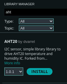
Finally, in order to not focus on the low-level details, we'll pull in a library. The Arduino IDE makes this really straightforward with the Library Manager. You can find it under Tools -> Manage Libraries... or in the left-hand sidebar where it has an icon showing a bunch of books. If you type aht into the searchbar of the window that opens, you'll find quite a few options! I just chose the first one AHT20 by dvarrel and clicked the Install button. Once it's successfully installed, let's use it in our program.
#include "Wire.h" // New library include
#include "AHT20.h" // New library include
#include <stdint.h> // New library include

const uint8_t AHT20_I2C_ADDR(0x38);
First we'll pull in the Arduino's I2C library with Wire.h, the sensor library with AHT20.h, and finally we'll pull in stdint.h which is a standard C library that defines a bunch of fixed-size types. This allows specifying that a variable is a uint8_t instead of an unsigned int. The former will always be a single byte (8 bits). The latter can change it's size based on the hardware that's being compiled to. Because every byte counts when you're working with hardware and if you send an extra byte the command you send to a sensor won't be understood at all! Define a bunch of constants for the I2C address and the two commands we need to initialize the sensor.
Since we noted the address number of the sensor from the datasheet as 0x38, I've also added a constant above the definition of the setup() function.
Next, let's go ahead and start reading data from the sensor!
// --snip--

void setup() {
    // --snip--
    Serial.println("info: booting");
    Wire.begin(); // initializes the Arduino's I2C hardware
    AHT20 aht20(AHT20_I2C_ADDR);

    bool initialized = aht20.begin();
    if (!initialized) {
        Serial.println("error: could not initialize aht20");
    } else {
        Serial.println("info: initialized sensor");
    }

    while (true) {
        while(!aht20.available()) {
            // If there's no data available, wait a little bit
            delay(10);
        }
        float temperature = aht20.getTemperature();
        Serial.print("data: ");
        Serial.println(temperature);
        delay(5000);
    }
}

void loop() {}
If you compile and run, you should now see something like this in your python script or in the Arduino IDE Serial Monitor:
info: booting
debug: sensor ready
info: initialized sensor
data: 25.72
data: 25.71
data: 25.71
data: 28.37
In the next chapter we'll modify our python program to parse that data from a string in the format "data: 13.37" into a decimal number that can be plotted or have other analysis performed on it.
Uploading Data to the Database
In this section we'll take our newly measured temperature data and parse it from the messages we're receiving from the Arduino. That data can then be uploaded into a database, in this case an InfluxDB instance. If you're following along remotely, see the appendix section on running InfluxDB with Docker.
We'll be using MQTT as a means of uploading data into InfluxDB. However the database also supports other means including a REST API, but it requires an API token to use. InfluxDB supports plugins for accepting data records via Telegraf, an associated project, and one of those allows subscribing to certain messages on an MQTT broker.
A Little About MQTT
MQTT is a means of sending messages between programs whereby the programs agree on a topic name like "temperature_data" and then the programs can publish data on this topic by sending the data to a broker or it can subscribe to data on this topic, again by talking to the broker.
In our case, the Python program will connect to the MQTT broker and send data to it by publishing to a topic. The InfluxDB/Telegraf instance will connect to the MQTT broker as a subscriber so that the broker will send it data. That data gets put into InfluxDB.
Using MQTT with Python
We'll be using a third party library from Eclipse called paho-mqtt in order to publish data in our python program. It doesn't require much code to get started:
import json
import paho.mqtt.client as mqtt
import serial
import signal
import sys

# --snip--

def main():
    # --snip--
    signal.signal(signal.SIGINT, exit_handler)

    mqtt_broker_ip = "192.168.5.100"
    client = mqtt.Client()
    client.connect(mqtt_broker_ip, 1883)
    client.loop_start()

    serial_port = serial.Serial(tty_path, 115200, timeout=1)
    serial_port.reset_input_buffer()

    while running:
        next_line = serial_port.readline()
        if next_line:
            next_line = next_line.decode().rstrip()
            print(next_line)
            if next_line.startswith("data: "):
                try:
                    temperature = float(next_line[6:].rstrip())
                    name = "ssnover"
                    client.publish(f"/temperature/{name}", json.dumps({"temperature": temperature}))
                except ValueError:
                    print(f"error: Could not extract data from {next_line}")

    client.loop_stop()
    print("Exiting...")

# --snip--
In the above code, we create a new instance of the Client class and connect it to an MQTT broker. I've set mqtt_broker_ip to the IP of the device on my network that's hosting the broker and port 1883, which is the default port for MQTT.
The MQTT library allows the user to handle an event loop in order to gracefully handle incoming messages if you're subscribed to any topics. Since we're not doing here, I've called Client.loop_start() and Client.loop_end() before and after the main loop. This just controls the starting and stopping of an additional thread which does the actual communication with the broker. If you were to leave this out, you'd actually see no data getting sent!
Finally, let's look at actually publishing the data. We know that the format of data messages coming from the Arduino is "data: [DECIMAL NUMBER]" so we first check that the line starts with that expected prefix. If it passes that basic check, we take everything after the prefix, remove any dangling whitespace characters with rstrip(), and then try to convert that to a float as a sanity check. This can throw an exception of ValueError if it's not a valid decimal number so I've just handled that by logging it and moving on. To finally publish, we need the topic name and the data. I use "ssnover/temperature" for the topic for the purpose of the in-person session so I suggest using your name in that pattern as well so the database can be ready to read it. The topic data is just a string format so we convert our temperature data back into a string.
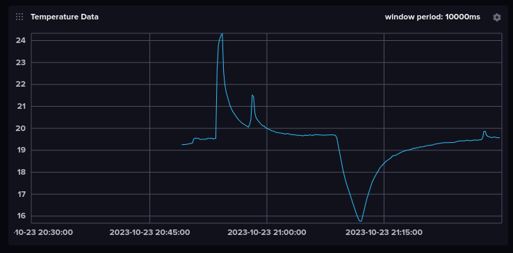
If everything is working correctly, you ought to see the temperature data coming in on the dashboard in the InfluxDB instance, go give it a look!
Demonstration with InfluxDB
A1. Hardware Required
If you're taking the class session in person, you can pretty much skip this page. This page is just documentation of the Arduino setup for those who are remote and interested in purchasing the hardware necessary to run the code for this course.
List of Hardware
These will mostly link to Sparkfun because they're local to me, but many of these items can be found on the usual sites including Adafruit, Digikey, Mouser, etc.
- Arduino UNO R3 (https://www.sparkfun.com/products/11021)
- Breadboard (https://www.sparkfun.com/products/12002)
- Jumper Wires (https://www.sparkfun.com/products/12795)
- AHT20 Breakout Board (https://www.sparkfun.com/products/16618)
You'll want to find a place where you can access a soldering iron in order to solder header pins on the breakout board. Check out your local makerspaces or libraries (which sometimes have makerspaces in them these days).
Circuit Diagram
The circuit is super simple, thanks to Arduino.
- Arduino 3V3 <--> AHT20 3.3V
- Arduino GND <--> AHT20 GND
- Arduino SDA <--> AHT20 SDA
- Arduino SCL <--> AHT20 SCL
Alternatively, Sparkfun is all in on their "QWIIC" connector (just a 4-pin JST connector). You can get a version of the Arduino UNO R3 with a QWIIC connector onboard and QWIIC cables; this will mean no soldering if you can't find that and don't own an iron already.
A2. Running InfluxDB
If you're running through this course asynchronously, you'll need to set up some software on your own computer in order to get to the big pay-off. This chapter talks through the set of software services I'll be running on my computer.
This part I'm less capable of ensuring runs on Windows and MacOS. I'm running this on Ubuntu 22.04 desktop edition using Docker version 224.0.4. You can find instructions for installing docker here: https://docs.docker.com/engine/install/ubuntu/
I'll be curt on explanation here and instead point to a repository with a working set of configuration files. The repository hosting them all is here: https://github.com/ssnover/mqtt-influx-config
You can run it while in the root directory with docker compose up -d which will launch three services: an MQTT broker, an Influx timeseries database, and an ingress service for the data that connects the two.
The first time that you run it, you'll be prompted to create an admin user, organization, and bucket on the webpage at http://localhost:8086. You'll also need to generate the API token with the UI. Once you've created these, edit the respective fields in the telegraf.conf file. If you host this for an extended period, make sure not to commit any files containing the API token. Relaunch the services with docker compose down and docker compose up -d and the new configuration should take hold.
If you've stuck with me this far, you must be interested in the subject matter!
This page will serve as a living list of links for additional writing I do for content that's related to this course which discusses different aspects of developing embedded systems. If there's a topic you're interested in and you don't see it here, feel free to send me a message!
I will also link to posts or writing that I've seen others produce on the topic of embedded systems so as not to unnecessarily reinvent the wheel on every topic.
Advanced Topics
Roll Your Own
- Reading an I2C Sensor with Arduino
- To Be Written: Creating Your Own Binary Protocol
- To Be Written: Publishing an Arduino Library
Rust
- To Be Written: Bare Metal IoT with Rust
- To Be Written: Using Rust for IoT Edge Devices